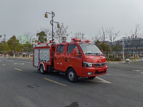
CLW5040GXFSG10/DF type water tank fire engine
(Dongfeng EQ1040D16DC chassis)
Technical Specification Sheet
- Vehicle Overview
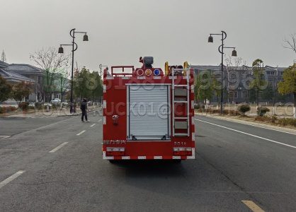
CLW5040GXFSG10/DF water tank fire truck, modified from Dongfeng Xiaoduolika, model EQ1040D16DC Type II chassis. The vehicle consists of two major parts: the cab and the body. The cab is an original double-row design that can accommodate 2+3 people. The vehicle has an exposed tank structure. The front part of the body is the equipment box, the middle part is the liquid tank, and the rear part is the pump room. The liquid tank body is made of high-quality carbon steel and is coated with epoxy primer and epoxy asphalt paint inside, with a load capacity of 850kg. Equipped with a CB10/20 low-pressure fire pump with a rated flow of 20L/S and a PS8/20W vehicle-mounted fire cannon on the roof. The most notable feature of this vehicle is its large fluid capacity, good maneuverability and easy maintenance. It can be widely used in fire brigades, factories, mines, enterprises, communities, docks and other places to fight fires.
The fire performance of the entire vehicle complies with the requirements of GB7956-2014 standard; The chassis is certified as a national compulsory product; Engine emissions meet the requirements of GB17691-2018 Stage VI limits (National VI standard); The vehicle passed the inspection of the National Fire Equipment Quality Supervision and Inspection Center and was approved by the Ministry of Industry and Information Technology to be included in the announcement of road motor vehicle products.
- Main parameters of the vehicle
| External dimensions (mm) | 5695 * 1780 * 2390 |
| Gross mass (Kg) | 4050 |
| Curb mass (Kg) | 2825 |
| Rated load capacity (Kg) | 850 |
| Maximum speed (Km/h) | 100 |
| Fire pump rated flow | ≥20L/s 1.0MPa |
| Fire cannon rated flow | ≥20L/s 0.8MPa |
| Fire cannon range (m) | ≥48 |
| Approach Angle/departure Angle (°) | 22/16 |
| The number of passengers allowed in the cab | 2 + 3 |
- Bottom plate
| Model number | Dongfeng Motor Corporation/EQ1040D16DC | 
Reference drawing, subject to actual supply. |
| Engine | Anhui Quanchai Power Co., LTD | |
| Model | Q23A-110E60 | |
| Power rate | 80kW | |
| Drive type | Rear-wheel drive | |
| Wheelbase | 3000mm | |
| Emission standards | GB17691-2018 National VI |
- Cab
| Structure | Flat-head, double-row four-door passenger compartment, all-steel frame welded structure. |
| Seating arrangement | Two people in the front row and three people in the back row. |
| Cab structure | Install a hydraulic tilting mechanism that is suitable for tipping and have anti-fall safety devices. |
| Cab equipment | In addition to the original vehicle equipment, add a power take-off control switch, a 100W alarm, a warning light switch, etc. |
| Exterior of the cab | A long row of warning lights is installed at the front of the cab roof. |
- Container
| Capacity | Water 850Kg (actual up to 1000Kg). | 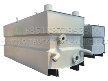 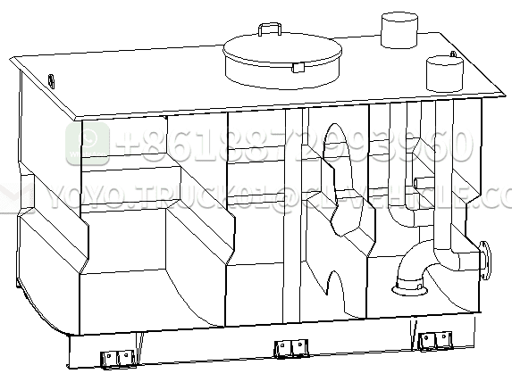
Reference picture, subject to actual supply. |
| Material | The water tank is made of high-quality carbon steel plate and treated with high-tech anti-corrosion technology. | |
| Structure | Frame welding, longitudinal and transverse anti-sway plates are set inside the tank to reduce the impact of water inside the tank during vehicle movement; The front and rear wall panels of the tank are folded with trapezoidal ribs to give the tank sufficient strength and rigidity. | |
| The top of the tank is equipped with quick-opening manholes for maintenance personnel to enter and exit. The tank is equipped with a device and a filter screen to prevent the water pump from creating vortices that could affect the flow rate. | ||
| The tank is equipped with a stainless steel float level indicator, which shows the volume of the fire extinguishing agent in the tank through the level gauge on the instrument panel; A drain with a ball valve is provided at the bottom of the tank. | ||
| The tank is equipped with two 76mm overflow pipes and one 65mm injection port on each side of the carriage for water supply and liquid addition. |
Equipment
1 entry hole with quick locking and opening device;
1 level indicator;
1 drain with stainless steel ball valve;
2 Water injection ports (one on each side).
“Process”
Weld firmly and reliably, remove and clean up defects such as slag inclusions and false welds; A 24-hour hydrostatic test should be conducted on the tank after welding to ensure no leakage.
- Fire pumps and piping systems
Fire pump
| Model | CB10/20 Low-pressure fire pump | 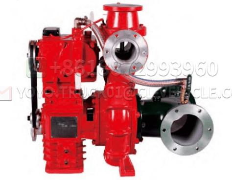
Reference drawing, subject to actual supply. |
| Flow rate | ≥20L/s | |
| Compressive force | Acuity 1.0 MPa | |
| Installation type | Rear-mounted | |
| True air pump | Piston type | |
| Vacuum pump material | Wear-resistant and corrosion-resistant, meeting the sealing requirements | |
| Drawing time | ≤35s | |
| Maximum suction depth | ≥7m | |
| Maximum vacuum degree | ≥85kPa |
Piping system
| Suction pipe | The pump is equipped with a Φ100mm inlet, which can draw water from natural water sources, liquid tanks, fire water storage tanks, and can be connected to a fire hydrant with a conversion reducer interface. The suction pipe is placed on the roof of the vehicle. 1 inlet with a Φ100mm butterfly valve for connection to the water tank. |
| Outlet piping | A Φ76mm fire hose and control valve with a flexible joint is installed on the roof; A Φ65mm manual ball valve is set on each side of the pump room. |
| Water injection piping | A Φ76mm pump water injection pipeline and control valve are set in the pump room; There is one Φ76mm water injection pipe on each side of the carriage, which can be used to inject water into the tank. The interface is an internal snap-on interface and is equipped with a cover. |
| Drain the water pipe | To protect the pump and the ball valves, drain pipes were added to the pipeline, each with a ball valve. |
| Cooling water pipeline | To enable the power take-off to handle various complex situations during operation, it is equipped with cooling water lines and control valves connected to the inlet and outlet water lines. |
- Fire cannon
| Model | PS8/20W fire cannon | 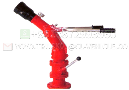
Reference picture, subject to actual supply. |
| Flow rate | ≥20 (L/s) | |
| Range | Water ≥48m | |
| Pressure | Acuity 0.8 MPa | |
| Position | Located on top of the water tank. | |
| Control | Manual control with locking mechanism for easy operation. |
- Power take-off
| Type | Full-power sandwich power take-off. | 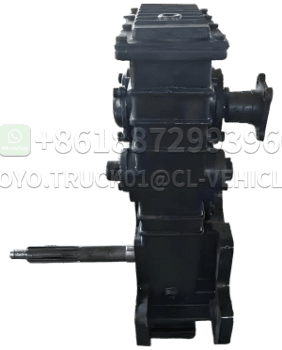
Reference diagram, subject to actual supply. |
| Cooling method | Forced water cooling. | |
| Lubrication methods | Splash oil lubrication. | |
| Operating methods | Operate the power take-off from the dashboard in the driver’s cabin. The power take-off fits smoothly without any noise. | |
| Installation | The power take-off fits well with the engine, fits precisely and does not come off on its own after engagement. |
- Equipment box and pump room
Main materials:
The frame and skin are made of high-quality carbon steel; The interior panels are oxidized aluminium sheets.
Basic structure:
- The overall structure features an equipment box at the front and a pump room at the rear.
- The rear pump room is equipped with a dashboard and operating system, and both the equipment box and the pump room have lockable roller shutters. The frame is welded and ensures its strength and rigidity.
- The space can be adjusted at will, and the equipment box has drainage holes.
- The equipment box is reliable, aesthetically pleasing, adjustable at will, and equipped with a large space curtain door equipment box to ensure full utilization of space.
- The carriage and pump room are equipped with lighting fixtures to meet the lighting needs during night fire-fighting operations.
Aluminium roller shutters:
- All equipment compartments and pump rooms are equipped with lockable roller shutters. The handles and lock pins are sturdy and durable, do not deform, and the sealing performance has been tested for water spray to ensure no leakage.
2 There are rivets in the tracks on both sides of the roller shutters to prevent them from falling off.
3 Each equipment compartment is equipped with a light that is controlled by the opening and closing of the roller shutter door.
- There are two aluminium alloy curtain doors on each of the left and right, and one at the rear, which are safe, reliable, beautiful and practical.
Basic principles:
(1) Design equipment integration according to combat formation and combat deployment;
(2) Design various equipment mounts according to ergonomic principles;
(3) The principle of simplicity and practicality in using any equipment inside the box without any climbing tools;
(4) Place equipment according to the logical relationship of use and frequency of use;
(5) Take out any equipment within 1-2 movements while standing on the ground or pedal.
- Electrical system
| 1. The cab top is equipped with a long row of red luxury warning lights. |   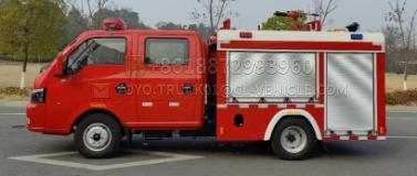
Reference picture, subject to actual supply. |
| 2. The alarm power is 100W. | |
| 3. One fire scene light is installed on the roof; Safety sign lights are installed on the lower sides of the vehicle, and reflective markings are affixed to the body and rear as standard. | |
| 4. All equipment boxes are equipped with LED lights for use in night combat lighting. | |
| 5. There are two flashing lights on each side of the vehicle, safety sign lights and side reflectors (combined type) on each side, front and rear outline lights, one turn signal on each side, and lighting in the passenger compartment, equipment box and pump room. | |
| 6. The alarm, warning lights, strobe lights and circuits are independent additional circuits, and the control devices are installed in the driver’s cabin. | |
| 7. All circuits are distinguished by their connection forms and functions. | |
| 8. The instrument panel in the pump room is equipped with a liquid level gauge, tachometer, pressure gauge, vacuum gauge, equipment box lighting switch, etc. |
- The instrument panel and the equipment on it
| 1. The dashboard is located in the pump compartment at the rear of the vehicle, with a control panel and adequate lighting. | 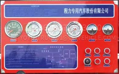
Reference picture, subject to actual supply. |
| 2 All control handles, switches, and indicator lights are marked in Chinese near them. | |
| 3. Instructions for operation are provided. | |
| 4. All signs are durable and highly attached, and can withstand the effects caused by sudden changes in temperature and climate. | |
| 5. The operation panel is made of high-quality boards, which are overall beautiful, durable and relatively light in weight. | |
| 6. The pump room operating system is located at the rear of the vehicle, with no pressure outlet to ensure the safety of the operator and panel lighting. |
- General Technical Requirements
- Technical requirements for the entire vehicle comply with the relevant requirements of GB7956.
- The appearance of the vehicle shall maintain a certain degree of flatness and comply with relevant regulations.
- All rivets shall maintain a certain density and comply with the enterprise standards.
- All welds are firm, smooth, flat and in compliance with enterprise standards.
- All operating switches, instruments, equipment racks and vehicles are marked with nameplates that comply with the specifications.
- Documents with the vehicle
| 1) Chassis user manual | 2) Chassis quality warranty card |
| 3) Chassis maintenance manual | 4) Chassis certificate of conformity |
| 5) List of on-board tools | 6) Fire engine user manual |
| 7) List of fire-fighting equipment for the fire engine | 8) Fire Engine Certificate of conformity |
Equipment List
| Serial Number | اسم | Units | Quantity | Notes |
| 1 | Fire hose | disc | 4 | 13-Φ65-20 4 discs |
| 2 | Suction pipe | meter | 4 | |
| 3 | Water filter | a | 1 | |
| 4 | Suction pipe wrench | a | 2 | |
| 5 | Ground fire hydrant wrench | a | 1 | |
| 6 | Underground fire hydrant wrench | a | 1 | |
| 7 | Guard belt bridge | a | 2 | |
| 8 | Cloth wrapped with water hose | a | 4 | |
| 9 | Hose hook | a | 4 | |
| 10 | Reducer interface | only | 2 | Φ65 to Φ80 |
| 11 | Switch the direct current water gun | the | 1 | |
| 12 | Flowering water gun | the | 1 | |
| 13 | Dry powder fire extinguisher | with | 1 | 3 kg, ABC dry powder |